|
Other guides:
This configuration guide explains how you can modify your WIFI Sensors
to sense the opening and closing of a tactile switch like a door/window switch used on alarm systems. We will explain how to wire the switch to your WIFI device, interface it with your PrivateEyePi alarm/monitoring system or interface it with your own system.
Firmware
You need to be on firmware version 1.9.7. or higher. Refer this guide to check you version and upgrade if required.
Quick Start
You can test the operation of a switch simply by bridging two GPIO pins. Once you have set up your WIFI device with PrivateEyePi (refer getting started guide above), use a piece of wire to short pin 14 with GND as shown in the following picture.

Figure 1 - Test a switch by connection Pin 14 to GND
Now go to your PrivateEyePi dashboard where you can monitor the status of the switch. When GPIO 14 is connected to GND then the switch is closed (i.e. door closed) and vice versa. Disconnect the switch from GND, refresh the PrivateEyePi page and the status light will now be red.
 Figure 2 - WIFI switch status on the PrivateEyePi dashboard
If you are on firmware version 1.9.8 or higher then you can configure an email rule by selecting Settings, Rules. The figure below shows a rule that will send you an email when the switch is open (i.e.d GPIO 14 is disconnected from GND). NB! Make sure you have configured your email address using the "Email" menu option).
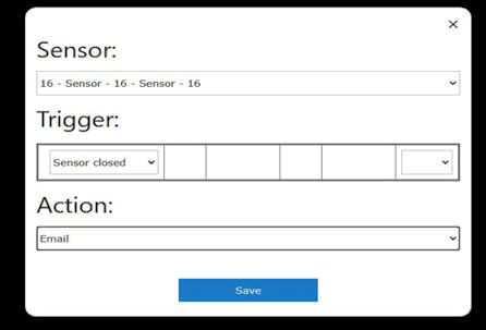 Figure 4 - Configure an email rule
Now you are ready for the real thing. Wire up your alarm system switches as shown in Figure 5:
 Figure 5 - A WIFI Alarm System
Switch Wiring
The WIFI sensor has six available input/output connections that you can use to connect external switches. Two of them are use for the temperature or temperature and humidity sensors so this leaves you with 4 connections for switches. If you remove the temperature sensor then you can connect 6 switches.
You gain access to the input/output connectors via the 16 pin header located on the right hand side of the WIFI board. Each connection is labelled 3v, 14, 13, 5, 3V etc...
Use the following table to plan your wiring:
As you can see from the above table pins 4,5 and 14 are readily available. If you have a temperature sensor then pin 12 is also available. If you have a temperature and humidity sensor then pin 13 is available.
You can make a fifth pin available by removing either the DS18B20 or DHT22 sensors, depending on which model you own. These sensors are labelled on the board (DS18B20 and DHT22). You can remove these sensors with a soldering iron or by cutting them off with a fine wire cutter or strong pair of scissors.
The sixth pin (pin 16) is available but requires some additional wiring of a pull up resistor circuit (1k and 10k resistor required). As shown in figure 16 you create a pull up circuit by placing a 10k resistor in line with the connection to the pin 16 and then a 1k resistor from the 10k resistor to the 3V pin.
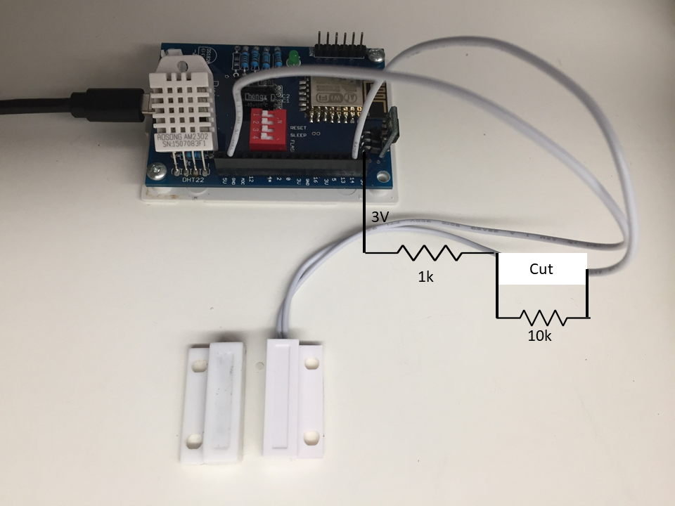 Figure 6 - Connect GPIO 16 to a switch via a pull up circuit
|
|
|
|
|
|