|
Once you have completed the setup of WIFI Temperature Sensor you may be interested in some of the advanced features of the device.
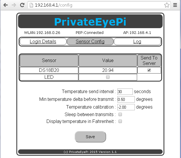
On the "Sensor Config" menu there are a number of options which we will describe further here.
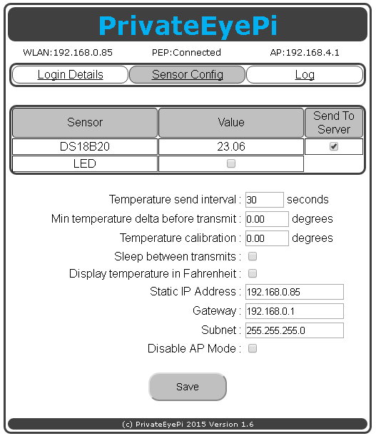 Send To ServerYou used this option in the setup tutorial to tell the sensor to send the reading from the on board DS18B20 temperature sensor to the server. Click the check box to send, and un-click it to stop sending.LED
On the older designs with and LED, the LED check box can be used to switch the green LED on/off. To switch it on click the check box and then click "Save". Do the reverse to switch it off. The LED will automatically switch on at the start of each temperature transmission and off once the transmission is complete.
This is the interval between temperature reading transmissions. For example if set to 300 then the sensor will send a reading every 5 minutes. Take note that if you are using the free PrivateEyePi service then setting it to below 300 may result in you exceeding the maximum daily message allowance.
Min Temp Delta Before Transmit
Set this to the number of degrees the temperature should vary (either higher or lower than the previous reading sent to server) before sending a new reading to the server. This is a very useful battery saving feature because the amount of electricity required to read the temperature is significantly less than WIFI transmission. Another useful use for this is to help not exceed your daily message allowance on PrivateEyePi. For example if you set the "Temperature Send Interval" to 10 and set the Min Temp Delta Before Transmit to 0.5 (Celsius in this example) then the temperature reading is fetched every 10 seconds but only sent to the server if the temperature has either increased or decreased by half a degree Celsius.
Temperature Calibration
The DS18B20 is accurate from
-55°C to +125°C or Fahrenheit equivalent -67°F to +257°F, ±0.5°C accuracy from -10°C to +85°C.
However you may want to adjust the readings to offset external influences.
Use this option to add or subtract a value from every temperature reading. For example if you set it to 2, then it will add 2 to every temperature reading, or -2 will subtract from every reading.
The on board WIFI chip will generate heat if powered on for long periods of time so you may find that this will skew readings. You can avoid this but using the sleep option described below or work around it by using the temperature calibration option to lower the reading. Another option is to remove the DS18B20 sensor and replace it with an external sensor.
Sleep Between Transmits
This option will shut down the WIFI sensor in between transmissions and automatically awaken the device for transmission every X seconds (defined by Temperature Send Interval) . This radically reduces the power intake of the device.
Take Note : The sensor will no longer be accessible through WIFI while it is in sleep mode. The device can be taken out of sleep mode by connecting GPIO 12 with 3V (as shown in the picture below).
This option must be used in conjunction with the "Sleep" dip switch on the board, as shown in the picture below.
6105.jpg?height=299&width=400) If you want to make use of this option then follow the following steps:
The device will now transmit temperature readings as per the Temperature Send Interval. On the older models with an LED, the LED will not switch on/off in sleep mode (further reduction of power usage).
Wake up from sleep mode
If you checked "Sleep between transmits" and want to take the device out of sleep mode then you need to set GPIO 14 high by connecting a jump wire between 3V and GPIO 14, set the sleep dip switch to the off position, and rebooting the device. Then connect to the device as you would normally do by using its ip-address or connecting to it as a WIFI access point. Navigate to the Sensor Config option, verify "Sleep between transmits" is unchecked then click save. This will clear the sleep setting. You can now remove the jump wire and and reboot the device. The device will stay awake and no longer sleep between transmits.
Display in Fahrenheit
The default temperature reading is in Celsius. Click this option to change the temperature readings to Fahrenheit.
Static IP Address
Enter the IP Address you wish to allocate to the sensor. This is useful if you are polling the device from another computer and do not want the IP Address to ever change.
Gateway & Subnet
These settings are mandatory if you want to set a static IP address. If you do not know the subnet mask and gateway of your router you can easily get it as follows:
Windows - Open a command prompt windows and type ipconfig, then page up and look for Subnet Mask and Gateway
Linux - Open a terminal session and type
netstat -nr. This will give you the Gateway. Now type ifconfig, and look for the Mask.
GPIO Pins
The 16 pin header on the right hand side of the board provides access to the General Purpose Input/Output (GPIO) pins. There are 8 GPIO ports available and then are numbered 0,2,4,5,12,13,14 and 16. The GPIO are used to connect external sensors like switches, motion sensors and temperature sensors. Even the on board DS18B20 temperature and DHT22 temperature and humidity sensors (where fitted) use the GPIO to send sensor readings. The table below describes the GPIO pin allocations and will help you plan for adding external sensors. In many instances a GPIO can support multiple functions, but not at the same time. You need to decide what how to make use of the GPIO pins available. Here are some example configurations:
- DS18B20 temperature sensor (pins 4 & 13) and 6 reed switches
- DS18B20 temperature sensor (pins 4 & 13) , 4 reed switches and 2 motion detectors
- DS18B20 temperature sensor (pins 4 & 13) , 3 reed switches, 2 motion detectors and a chime
- DHT22 temperature sensor (pins 4 & 12), 2 relay switches and 4 reed switches
- 8 reed switches
- 8 relay switches
Legend
P - Provides power to the temperature sensors
DHT22 - Temperature and humidity sensor (where fitted)
DS18B20 - Temperature sensor (where fitted)
A - Awake pin (wakes the sensor if asleep - see advanced configuration)
R - Pin that can use used to control a relay (external high voltage circuit switch)
S - External switch (reed switch, button switch, motion sensor, water sensor)
* - DHT22 uses pins 12 and 4 (provides power to the DHT22 sensor)
** - DS18B20 uses pins 13 and 4 (provides power to the DS18B20 sensor). You can connect multiple DS18B20 sensors to pin 13 (see figure 2 here for more details)
*** - Pin 16 requires an external pull up circuit to operate as a switch
****
- When GPIO is connected to GND the Blue light on the WIFI chip will turn on. This is
normal behavior.
Adding analog sensors to the device
From version 1.9.9. we added the ability to add analog sensors to the device. The Analog sensor GPIO pin is labelled ADC, but the label is a little difficult to read. It is the third GPIO pin from the bottom of the board (ie 5V, GND, ADC,12..).
We have added an analog sensor value to the Sensor Config menu option screen. You can also query the analog reading using the /analog url:
e.g.:
http://your-sensor-ip-address/analog
The reading will be a value between 0 and 1024.
Wire whatever analog sensor you want to monitor the same way you would wire it to an Arduino. Except the Arduino has 5 analog pins, and the IOT WIFI sensor only has one. There are plenty of wiring documentation online for Arduino.
Reboot (power off and on) the sensor in order for these settings to take affect.
|
|
|
|
|
|