|
Note: Prior to this tutorial you need to complete setting up the base station receiver and testing the RF Multi Sense Sensor.
This tutorial involves soldering a switch to the Multi Sense Sensor button contacts as shown in Figure 1 below.

Figure 1 - Solder your switch to the button contacts
When the contacts are joined (bridged) or separated the sensor will transmit a message indicating the change in state.
Messages transmitted when contacts bridged (switch closed):
a02AWAKE----
a02BUTTONON-
a02BUTTONON-
a02SLEEPING-
Messages transmitted when contacts not bridged (switch open):
a02AWAKE----
a02BUTTONOFF
a02BUTTONOFF
a02SLEEPING-
Note: Notice above that two BUTTONON/OFF messages are sent every time the switch state changes. This is merely precautionary in case one message is missed by the receiver. The number of messages can be configured using the NOMSG command (see sensor manual for more details on that).
Note: You can connect any tactile switch that opens and closes a circuit to the RF sensor. E.g. push button switch (like a door bell), or an on/off switch, a magnetic switch (e.g. for alarm systems), a vibration switch, water sensor etc...

Figure 2 - RF Multi Sense Sensor connected to a magnetic switch
Normally closed switches
If you have a normally closed switch that you bought from our store it will have three wires (white, black and gray). It is actually a normally open or a normally closed switch and therefore has three wires. Use white and black for a door/window that is normally closed, or alternatively use white and brown for normally open configuration. See Figure 3 for how to attach it to the wireless sensor in the normally closed configuration.
Note: We received a batch of switches with a brown wire and two white wires. In this case we have labelled which white wire to use. The other wire to use in this case is the brown wire.
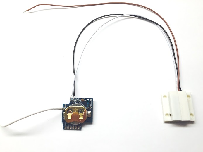 Figure 3 - A normally closed switch configuration (attach black and white wires to the wireless sensor)
If you bought the water sensor from us you may have received three parts as shown in Figure 5. You do not need the part on the left. Cut off the connector of one side of two of the wires and strip off the shielding so you can solder it to the RF sensor, as shown in Figure 4.
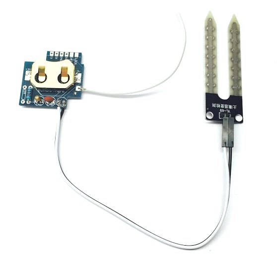
Figure 4 - RF Multi Sense Sensor connected to a water sensor
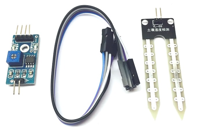
Figure 5 - Water sensor parts
You are almost ready to complete the installation. All you need to do now is place the sensor in the case. Carefully thread the antennae through the hole of the case, as shown in figure 1.Be careful not to pull the antennae as this could cause it to break off.
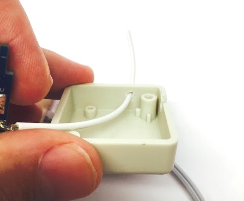
Figure 5 - Thread antennae through the case
Use the second hole in the case to thread the switch wires through. However I find it easier cut open the second hold so that you can place the sensor in the case without having to thread the switch wires through the hole, as shown in Figure 6.
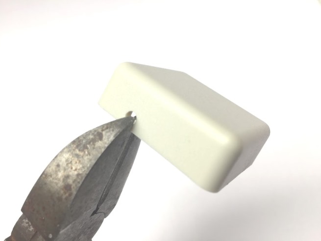 Figure 6 - Cut open the second hole in the case with wire clippers.
Now place the sensor in the case as shown in Figure 7.
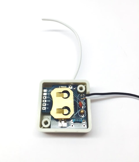
Figure 7 - Place sensor in the sensor case
Lastly fasten the base of the case using the two screws that came with your kit as shown in Figure 8.
56bb.jpg?attredirects=0) Figure 8 - Close the case with screws
That's it! Now you are ready to configure your Raspberry Pi to receive the temperature readings. Follow the steps outlined on our wireless sensor page.
|
|
|
|
|
|