|
The WiFi Wireless Gateway Version 2 can be updated directly over the web!
When new firmware is available, an update option will appear at the bottom of the Setup Details screen shown below. 
The "Update Gateway" selection will appear when it checks with the download server and finds a software update. When you are ready to update the Gateway, select YES and Save. When the update starts, the screen will clear and a green status bar will appear. 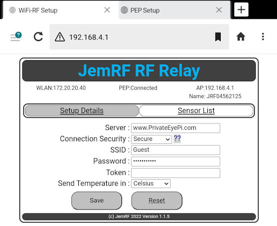
Once update is complete:
- It should reconnect to the Internet then restore the AP update page. - Some wireless networks have issues using the internal 192.168.4.1 address. If your Gateway Shows updates even after doing an update, try using the local WLAN IP address to do the update. Manual updates using Windows .jpg) .jpg)
For the Wireless Gateway Hardware the 3.3V FTDI can plug directly into the header on the PCB, and does require wires.
2. On the Sensor, set dip switch 3 and 4 (marked FLASH) to ON
8750.jpg?attredirects=0)
3. Check the device manager to determine the com port assigned to the FTDI
f823.jpg?attredirects=0)
4. Download, unzip and run the ESP Flasher (file attached below)
5. Set the COM port, select the bin file (files attached below)
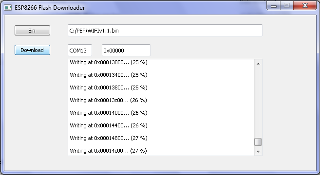
6. Reset the device by setting dip switch 1 ON then OFF, then click Download.
-- Note: Messages will start tracking the install which will take about a minute. 84b8.jpg?height=173&width=200) 181f.jpg?height=176&width=200)
7. The device will automatically restart after the new firmware is uploaded. Set dip switches 3 and 4 back to the OFF position.
Its generally a good idea to reset the device using the
Reset
on the Login Details screen. Sometimes when we add new code we use different parts of the device memory so you may see erratic data displayed on the config screens. Resetting the device will reset the memory on the device to work with the new version. If the config screens are not visible you can also reset the device using the URL : http://192.168.4.1/reset
Release Notes:
Version 2.3.0 (12/27/2022)
- Support MQTT Broker user defined publish and Client Id
- Sensor List show GMT time when refreshing
Version 2.2.0 (07/27/2022)
- Load for Version 2 hardware
- Supports web firmware download and Update from Setup Page
- Supports MQTT Agent to send to MQTT Broker
Version 1.1.5 (03/22/2022)
- Operational Baseline Load
|
|
|
|
|
|
