|
This sensor comes with a motion sensor for detecting motion, but it can also be used with any switch that opens/closes the circuit. It can also be used with a water sensor.
What you need
How it worksThe wireless sensor will transmit movement signals each time the Btn contacts are closed (bridged) - refer Figure 1. The signals are received by the base station receiver. The transmitter is optimized for extremely low current consumption and battery life will depend on how many transmissions the device makes. The RF units are very powerful and should easily handle communications distances around a residential home. The transmitters come pre-configured with a unique number identifier that will be used to uniquely identify each sensor. This enables you to have as many wireless switch sensors as you want. The Python code required to read the switch messages from the serial communications port of the Raspberry Pi is provided by us. We also provide the code to send the switch values to the PrivateEyePi server to be displayed on your WWW dashboard; however this is not a mandatory part of this project. If you want a wireless switch sensor for other projects then these steps will help you achieve that goal too. 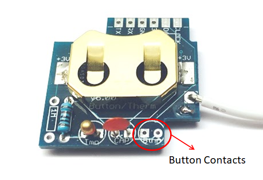 Figure 1 - Button Contacts to connect the motion sensor Construction Connect the motion sensor to the transmitter as shown in Figure 2. You may find the circuit somewhat confusing so I will explain how it works : The wireless transmitter (top left) will send a signal when the two contacts (Refer Figure 1) are closed (ie bridged). The three legged transistor in the middle of the breadboard acts as a switch. It will close the circuit between the outer two legs of the npn2222a transistor when a signal (3V current) is sent to the middle leg. The motion sensor sends 3V current to the middle leg when motion is detected. Both devices (transmitter and motion sensor) have two separate supply voltages (3.3V for the wireless switch, which uses a 3.3V coin cell battery and 4.5V-20V for the motion sensor, e.g. 4xAA or a 9V battery). Don't use 3x1.5V batteries for the motion sensor as it is too close to it's 4.5V minimum boundary, rather use 4x1.5V.
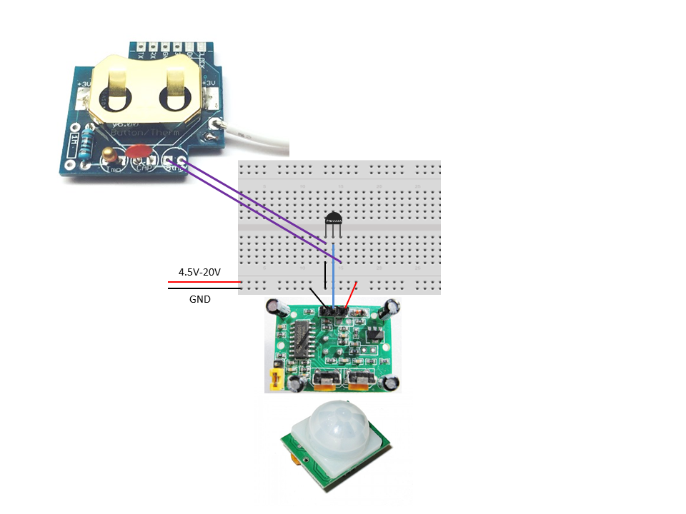 Figure 2 - Wiring diagram for the Wireless Motion Sensor
That's it! Now you are ready to configure your Raspberry Pi to receive the on/off messages. Follow the steps outlined on our wireless sensor page.
|
|
|
|
|
|