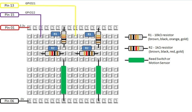
Above and below are the diagrams of the electronics that will interface the alarm system sensors with the Raspberry Pi. The first diagram is a conventional electronics schematic and the second is how you can build the circuit prototype on a bread board. We have shown two identical circuits representing two contacts in your alarm system. You can repeat the pattern as many time as you like, but within the limitations of the number of available IO ports on the Raspberry Pi.
The Magpi Magazine is a
n excellent resource for learning electronics on the Raspberry Pi. Refer issues 2 & 3 for deeper explanation behind the electronics shown on this page. The diagrams below are adaptions of the circuits in Magpi Issue 3.
The switches in the diagrams are the door contacts or the motion sensors of the alarm system. Door contacts (known as reed switches) are the easiest to work with and probably a good starting point. A reed switch has two halves, one half goes on the door and the other half goes on the door frame. The half on the door frame contains a magnet that holds the switch closed when the door is closed. When the door opens the magnet is no longer holding the switch closed and the circuit is broken triggering the alarm.
A motion sensor (known as PIR) is more complicated because it is a powered device. The circuits below don't provide power for an external electronic device. As a general rule DO NOT use the Raspberry Pi to power external electronic equipment, unless you have a very good understanding of how much power it is going to draw. PIR sensors are not standard and come from many different manufacturers and require power sources specified by the maker of the device. You will need to do a bit of research on the PIR sensor you intend using before connecting it to your alarm circuit board. Often PIR sensors have four wires, two for power and two for the alarm circuit. In this case you will connect the two wires for the alarm circuit to each side of the switches in the diagrams.
More details on the motion sensor we provide from our store available here.
If you already have an alarm system installed and you decide to disconnect some sensors for this project, please note that depending on where you live there may be bylaws that require a professional technician to do the work for you.
Figure 1 - Electronic Circuit
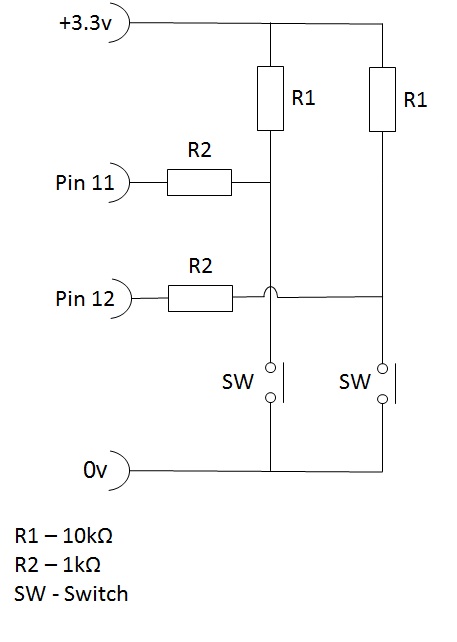 Figure 2 - Bread Board Circuit
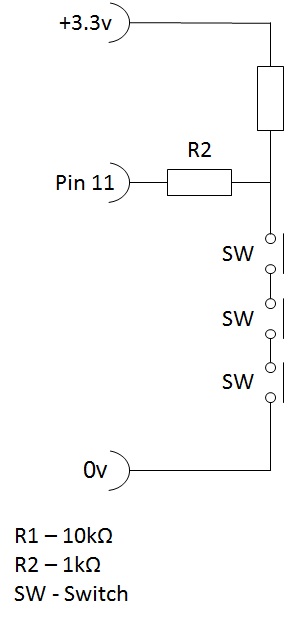
In
figure 3 below we show how you can connect multiple switches to one IO
port. If you already have an alarm system installed it is likely that
you have multiple sensors chained together and connected to a single
zone.
Figure 3 - Connecting multiple switches in series to a single General Purpose IO port
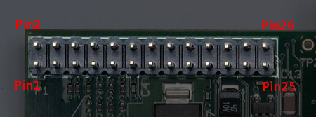
 Use female to male jumper cables to connect the pins of the Raspberry Pi. You can use a ribbon cable like this to build a more permanent solution.
As per the diagram below there are 8 GPIO pins (dark green in the diagram) you can use for alarm switches. However you can configure other pins for I/O, which then gives you access to 17 I/O pins in total, which equates to a 17 zone alarm system. See this link for further details on GPIO :
|
   |
|
|
|
|
|